1. Forward Kinematics
Summary:
For this project, the RPI robotics toolbox (ROX) was used for calculating forward kinematics of the Dofbot. The ROX toolbox uses the product of exponentials method (PoE) for mapping the links of the robot spatial kinematic chain.
Theory:
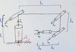
The PoE method essentially multiplies and adds the rotations and position matrices between links in a robot with a predefined zero condition. In the case of the Dofbot we had five (5) revolute joints in a chain attached by straight links. We define the h-axis for the robot as the rotation axes for each joint relative to the base frame O. This defines the coordinate frames for each joint.
The next step becomes defining the position vectors for the link lengths relative to each respective coordinate frame defined previously based on the rotation axes. These can be defined by multiplying the lengths in their respective unit vector directions and defining a 3D-P vector.

After everything is defined, positions for the joints and most importantly the end effector can be calculated. The equation for the end effector position (full multiplication of the kinematic chain) is shown in Figure 2.

With this fundamental knowledge, it can be applied into calculating robot positions. In the case of the project, a robotics toolbox was used.
Application:
This theory was applied by using the ROX toolbox and doing checks in the MatLab robotics toolbox and scripts provided from the course notes.
In ROX, we can define the robot dimensional matrices by defining three structures: H, P and joint_type. H is a matrix that defines through which axes the rotation of the joint is occurring for all the joints. This vector lists all of the joints consecutively, as do the other two structures for defining the arm joints. P is the matrix that defines each of the joint lengths relative to the zero-configuration base frame. And the joint_type matrix consecutively defines the type of joint in the kinematic chain. In the case of the Dofbot where the joints are all revolute, they are all identified by a zero.
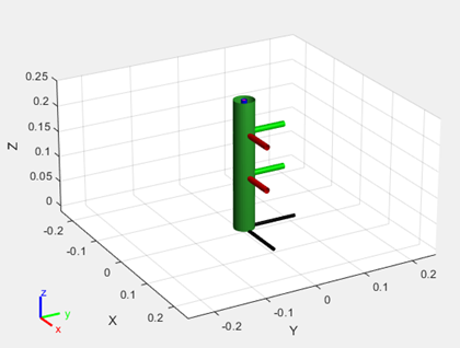
In the figures below, it shows the structures filled in for the zero configuration used in our implementation of the Dofbot. And also the simulated Dofbot in Matlab.


Contact Me
Email: michael.aksen@gmail.com
LinkedIn: https://www.linkedin.com/in/aksenm/