4. Path Following w/Feedback
Summary:
For the Dofbot, PID was implemented and demonstrated in a separate path to the PnP operation. Some velocity control was tested in the beginning of the project for the path, but we found that it did not significantly improve the smoothness of the path for the PnP or etching tasks. Therefore, a joint-based position control functionality was implemented. Joint-based control allows for the retention of R0T changes that could not be constrained if end effector position, P0T, was controlled for the PID code instead. Position-based control was performed for all five joints that control end effector position concurrently. After some tuning, a stable system was demonstrated with live-feedback from the Dofbot (shown in Figure X).
Theory:
PID control, which is a form of closed-loop feedback control, is used in systems where there may be sensor-noise or just general system noise and errors that may prevent a standard open-loop system from reaching its target values. Therefore, PID control is implemented to ensure the system reliably reaches its target value. The behavior of the system, including its overshoot, settling time, rise time, and steady-state error can be controlled by the PID parameters: Kp, Ki, Kd. The standard PID block diagram is shown below:
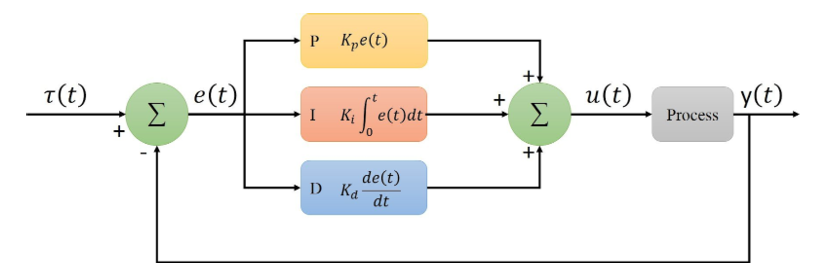
This block diagram shows the target value of the system, Ƭ(t), the current value of the system, y(t), the subsequent error, e(t), and the correction factor that is applied to the system, u(t). The error term needs to be processed through the proportional, integrator, and derivative controllers to determine the correcting factor to be applied to the next step. The proportional controller just applies a correction factor to the current error term. The integrator controller applies a correction factor to the total error accumulated over a period of time. The derivative controller applies a correction factor to the change in error from the previous time-step. The behavior of the system can be controlled by modifying these individual correction terms. The step-response plot is shown below, which depicts how a real-system may respond to a unit step change in the target value.
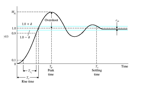
The step-response plot shows several parameters that characterize the behavior of the system. The rise time is the time it takes to go from 10% to 90% of the desired change. The settling time is the time it takes to get within a few percent of the target value, typically 1-5%. The overshoot is a percentage that describes the amount that the system overshoots past the desired value. Finally, steady-state error describes how much error remains in the system once the response stabilizes.
Application:
For our application of feedback-based control, we followed the pseudocode diagrammed by Dr. Oakes, which describes the discrete-time implementation of PID control to apply it to the Dofbot. We first programmed the functionality in a local python environment and simulated the current step by using the output from the previous step as the reading for the current step value. This translates to setting the system/process block in Figure I equal to one, or assuming the system is perfectly stable with no noise or error. This resulted in the plot below.
Once the functionality with these PID parameters was implemented with live-feedback from the Dofbot, it proved to be unstable. The video of these results can be seen in Figure IV. For context, the results without live feedback can be seen in Figure V. Therefore, tuning needed to be performed on the PID parameters to achieve a more stable system. Following the diagram in Figure VI, we increased Kd and decreased Ki and Kp to decrease overshoot and instability in the system.
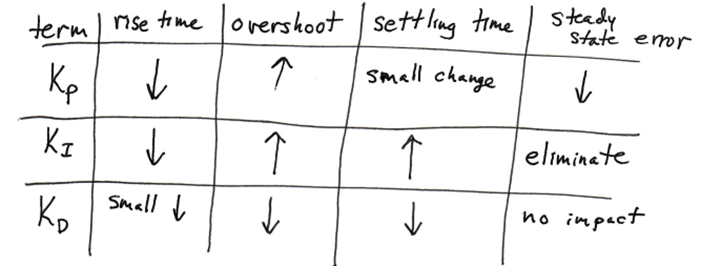
There were warnings about increasing the derivative term in noisy systems, but the large derivative term did not cause any issues for our system. Our final parameters are shown in the table below, along with some parameters of the system for a test run we performed with the feedback-control.
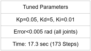

The joint plots corresponding to this test run and system parameters are shown below.
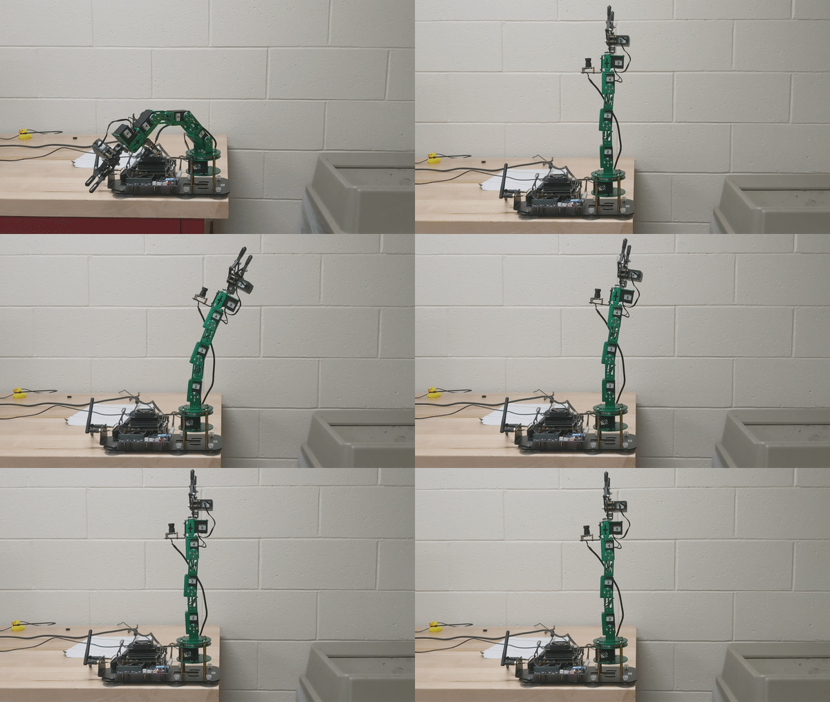
These system parameters were tested on the Dofbot and the results are shown in Figure X below. In the future, we hope to implement the PID functionality with the object-avoidance algorithm to move from one point to another accurately while also avoiding obstacles in its path.
Contact Me
Email: michael.aksen@gmail.com
LinkedIn: https://www.linkedin.com/in/aksenm/